| MAGNABEND HANDYMAN MODEL |

ELECTRICAL CIRCUIT AND ELECTRICAL ENCLOSURE
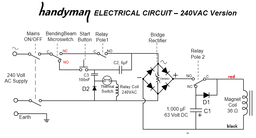
Compared with previous Magnabend machines the circuit for the Handyman machine has been redesigned to make it simpler and with lower component cost .
The most significant improvement relates to how the demagnetising is achieved. Previously this was done with a reverse pulse supplied from a pre-charged capacitor. In the new circuit no pre-charge is necessary, but rather the demagnetising capacitor (C1) recovers sufficient energy from the residual energy that exists in the magnet following turn-off.
This leads to a simpler, but equally effective, circuit and the machine is left automatically demagnetised after each bending cycle.
 Note:
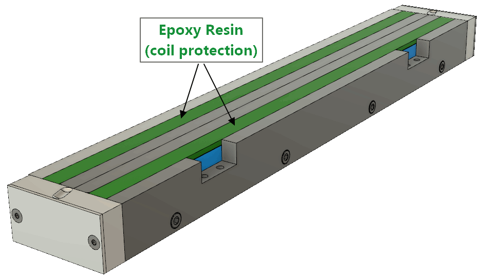
Note: This new circuit requires that the protection for the magnet coil is done with epoxy resin (or posibly non-magnetic stainless steel strips).
An earlier design for Magnabend machines used aluminium strips to protect the coil but these cannot be used with the new circuit as they would be too conductive of eddy currents and hence would cause too much damping in the magnet.
COMPONENTS:
The components required to build the Handyman circuit have been carefully researched for cost effectiveness. Most of them are available from the global supply companies RS Components or element-14. However sufficient details are provided for each component to enable you to source them from any supplier of your choice.
The prices, in Australian Dollars, were correct at the time of publishing this web page. Many of the smaller items will be subject to minimum order quantities; for instance the diode must be purchased in a pack of 10. Thus overall cost for the diode will be ($0.54 x 10) = $5.40.
If you source the components from the suppliers shown below then the total component cost, per Handyman machine, will be around $60.
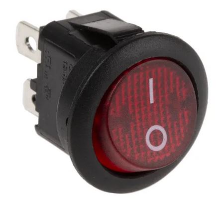 Mains ON/OFF switch. Illuminated rocker, 10 Amp Panel hole dia 20mm RS Components No. 468 5380 Approx price $5.80 |
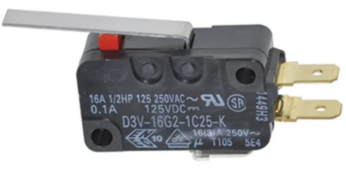 V3 Microswitch SPDT, 16 Amp Snap-acting. RS Components No. 807 3873 Approx price $5.00 |
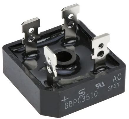 Bridge Rectifier 35 Amp, 1,000 Volt, Screw mount. Element-14 No. 2675368 Approx price $4.25 |
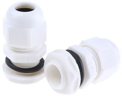 Cable gland/ clamp, Hole dia 16mm, Suits 5~10mm cable RS Components No.818 8127 Approx price: $1.10 |
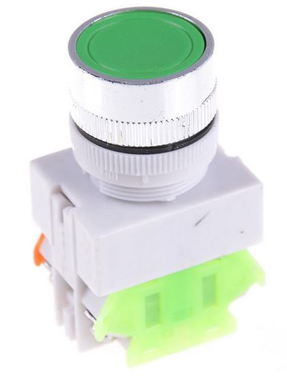 START button, 22mm. Momentary pusbutton 10A @ 250V AC Zhenzhen-1 (eBay) Approx price: $4.00 |
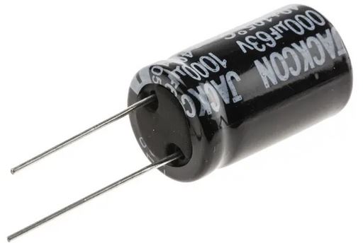 Demagnetising Capacitor, C1 Electrolytic 1,000uF, 63 Volt, RS Components No.711-1637 Approx price: $2.10 |
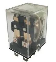 Relay, DPDT 230 Volt ac coil, 10 amp Element-14 No.2811455 Approx price: $6.90 |
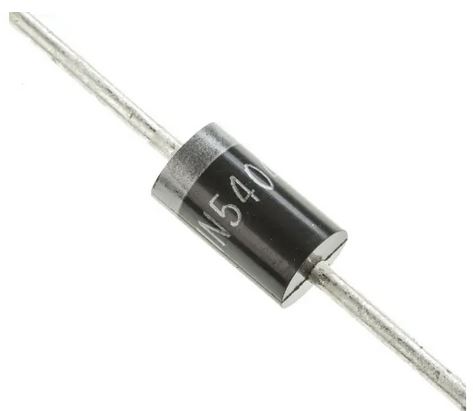 Diode, 1N5404 (D1,D2) 3 Amp, 400 Volt RS Components No. 628 9473 Approx price $0.54 |
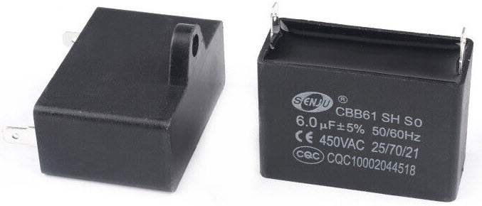 Pre-Clamping Cap.(C2) 6uF, 450 V ac (Fan motor type) Designation: CBB61 SH eBay price : $9.80 |
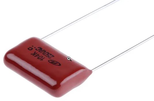 Coupling Capacitor (C3) 100nF, 250V ac 18.5 x 13.7mm x 6.4 RS Components No. 755-4260 Approx price $1.70 |
 Metal Oxide Varistor Clamps at: 650 volts, Clamping current: 50 amps, RS Components No. 800-7059 Approx price: $1.00. |
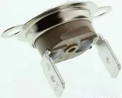 Thermal Switch. SPST, 10 Amps Open/ Close: 60/45 C Jaycar Cat # ST3821 Approx price: $6.50 |
 Terminal Block 12-way, 12 AWG, 32 A With wire protectors. RS Components No.840-7951 Approx price: $3.50 |
 Crimp Terminals Female insulated spade 6.3 / 0.8mm RS Components No. 534 351 Approx price $0.28 each |
 Crimp Terminals To suit tabs on the relay. 4.8 / 0.5mm RS Components No. 245-5193 Approx price $0.29 each |
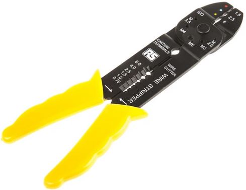 Crimping Tool for insulated terminals Length: 206mm RS Components No. 534-812 Approx price: $20.00 |
Suggested Hook Up Wire:
0.75 mm2, 30m reel, strands: 6/0.25 mm, RS Components No. 687-7544. Approx price: $23.00/ reel.
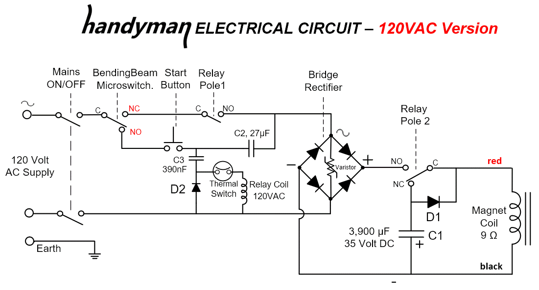
ELECTRICAL CIRCUIT - 120 VOLT VERSION.
Compared with the 240 Volt version of the circuit above this 120 Volt version will have twice the current but all the components can have a lower voltage rating.
Many of the components can remain the same, but note that all of the capacitors need to have 4 times the value (but only half of the voltage rating), and the relay will need to have a 120Vac coil.
The diodes can remain the same (1N5404) as they have to conduct only small currents in either version of the circuit, and likewise with the bimetallic switch.
The V3 microswitch is rated at 16 amps so it too can remain the same.
The suggested bridge rectifier will suit either circuit as it has generous voltage and current ratings.(1,000 volts, 35 amps). The varistor, if fitted, can also remain the same as its clamping voltage (650) is under the voltage rating of the bridge.
The magnet coil will have 4 times less resistance (9 ohms instead of 36 ohms) but will consume the same amount of power. (Power = Voltage x Current).
The physical size of all the components will be about the same in either version of the circuit.
The relevant Standard for the design of the electrical circuit is: IEC 60204-1 "The Safety of Machinery".
ELECTRICAL ENCLOSURE
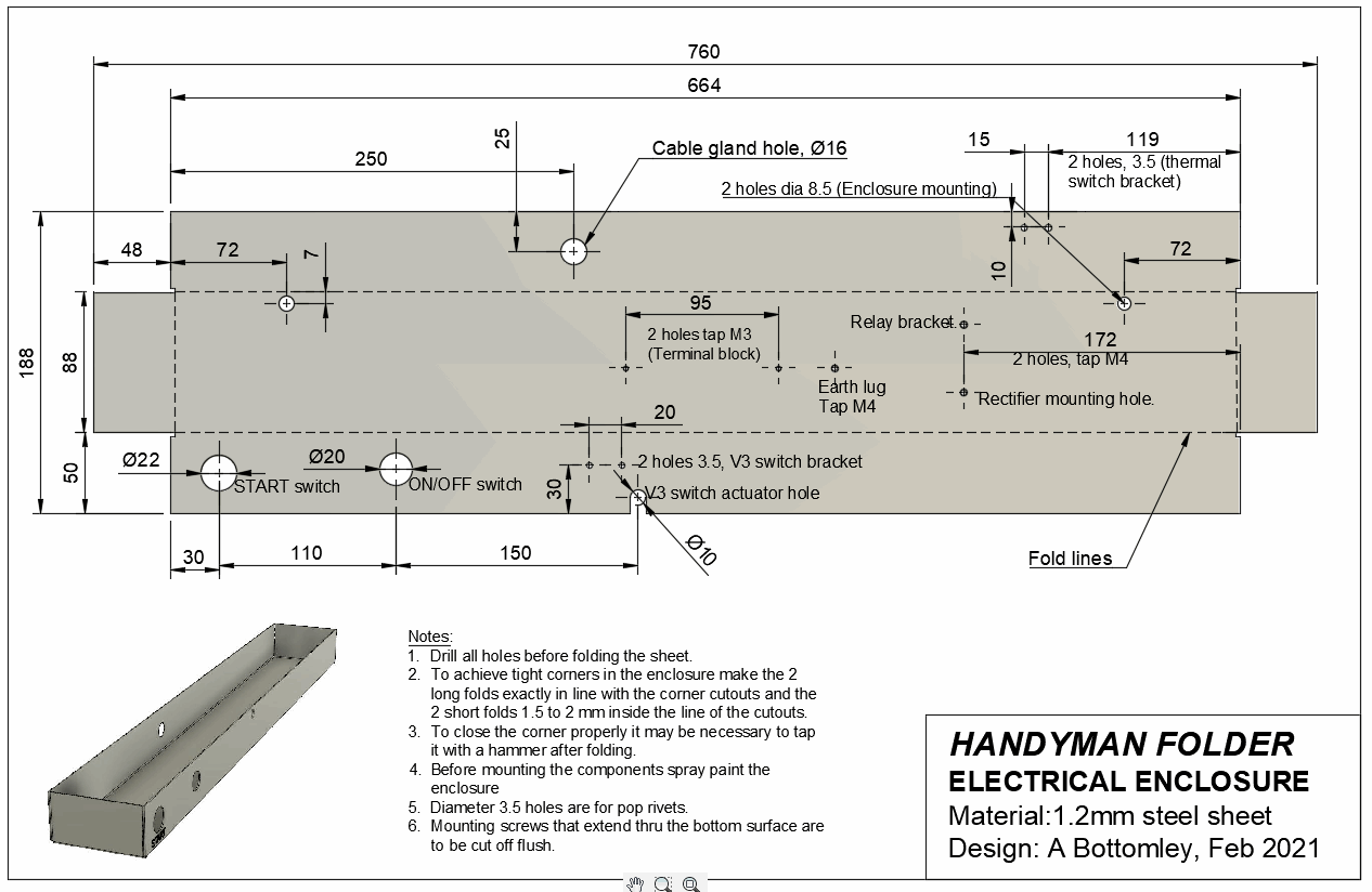
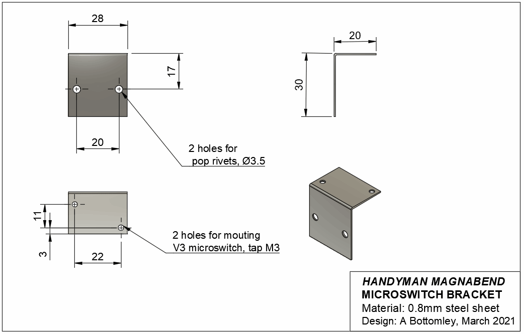
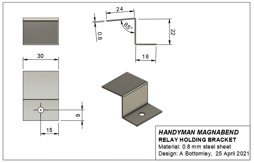
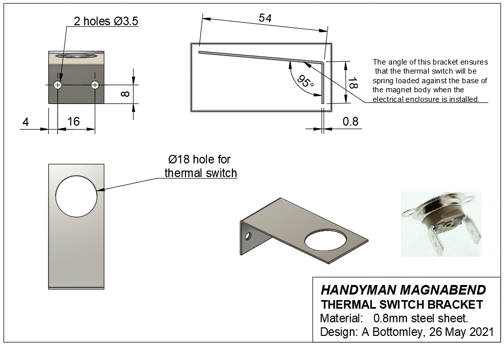
Electrical Enclosure Brackets and Mounting Bush, (click the drawings to enlarge):
Electrical
Enclosure with brackets, terminal block and bushes installed:
(click
the picture to enlarge).

The
electrical enclosure is attached to the underside of the magnet body
using two M8 x 60 long screws.
Each screw passes through a bush. The bushes are floating but will become clamped once the mounting screws are tightened.
Electrical Enclosure photo showing the completed assembly. (click the photo to enlarge).
Each screw passes through a bush. The bushes are floating but will become clamped once the mounting screws are tightened.
Electrical Enclosure photo showing the completed assembly. (click the photo to enlarge).

- Before installing the wiring it is advisable to insert an insulating sheet under the terminal block area.
- The recommended terminal block includes wire protecting leaves. To help ensure that wires are not inserted on the wrong side of the leaves it is best to have the clamping screws fully un-wound before inserting the wires.
- After tightening of the terminal block screws test the connections by pulling on the wires.
- The demagnetising capacitor is an electrolytic type and that means that it is polarised and must be connected with the correct polarity. The circuit diagram shows that its positive lead is connected to the negative side of the magnet coil. That may look wrong but the capacitor gets negatively charged with respect to the normal coil voltage polarity and it is most important that the capacitor is connected as shown in the circuit diagram.
Waveforms in the Magnet
Coil and Flux in the
Magnetic Circuit
The following information is included for the interest of readers. It is not needed for the construction of the Handyman folder.
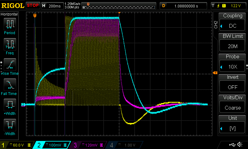
The oscilloscope traces below plot magnet parameters against time and show what happens in the magnet during a bending cycle:-
The magnet coil voltage is represented by the yellow traces,
The magnet coil current is represented by the pink traces and
The magnetic flux in the steel is represented by the blue traces.
Magnabend Waveforms
The above set of traces shows an overall picture of
a complete bending cycle from light clamping,
through full clamping and the
demagnetising phase which follows the turn-off of power to
the coil.All 3 traces were captured simultaneously on a digital oscilloscope (Rigol model DS1054Z).
From a demagnetising point of view it is important to note that the magnetic flux (blue trace) becomes negative before settling to zero at the end of the cycle. Because of hysteresis in the magnetisation it is necessary that the magnetic flux actually reverses in order to cancel out residual magnetism.
For an in-depth analysis of Magnabend waveforms please go to this page:
http://aaybee.com.au/Magnabend/Handyman_Pages/Handyman_Waveforms.html
This
page last updated: 26 May 2021
