Contact Alan Magnabend Homepage Alan's Homepage
| HOW TO BUILD A MAGNABEND |
The first thing to do is to read the articles on this website about Magnabend - Fundamental Design Considerations and Magnabend Circuit Operation.
The information given here is of a general nature only. The constructor will need to work out details, such as where the screws go etc, themselves.
Update:
A complete set of dimensioned drawings have now been added for a small machine.
See here: https://aaybee.au/Magnabend/Magnabend_Handyman_Model.html
I will assume that you have a fairly good workshop otherwise it is doubtful whether this project should be attempted.
Next decide what type of magnet cross section that you would like to build. Unless you have very good milling facilities then I suggest that you go for a U-type magnet body. Although this design is not quite as efficient as an E-type body it is quite a bit easier to build and in fact can be built without any milling, especially if you can obtain cold rolled steel sections. (Cold rolled steel has a nice accurate finish and no mill-scale on the surface).
(If you want to build an E-Type magnet then there is an example model at the end of this page).
The above drawing shows the basic arrangement of components in a U-type Magnabend.
Next you need to decide what thickness of sheetmetal you would like to be able to bend.
I will suggest a design which will be able to bend 1.2mm (18 gauge) mild steel or aluminium. ( If you need more capacity than this then you will have to use thicker sections than those suggested below).
I will also assume that a fairly limited duty cycle will be ok for hobby use. This will allow a more compact magnet design with a bit less steel and a bit less copper wire.
Suggested Hobby Magnabend cross section:
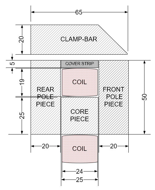
Note: All dimensions are in millimetres
- Note: The beveled edge
of the clampbar is not essential but the machine will be more versatile
if this can be provided.
The
Cover Strip over the coil must be a non-magnetic material otherwise it
will short-out part of the magnetic flux and thus cause loss of quite a
bit of clamping force. It is suggested that the cover strip be
aluminium.
In commercial Magnabends the cover strip is supported on small rebates milled into the poles on either side. However to avoid the need for milling, the cover strip could be supported on a layer of polyester resin (body-filler) between it and the coil. (Clamp it flush with the surface until the resin sets).
Nearest imperial dimensions can be substituted if desired eg 3/4" instead of 20mm, 2" instead of 50mm etc.
- For best performance the
Core Piece should be the
same length as the pole pieces as shown in the perspective
drawing above.
Although it is tempting, and certainly possible, to make the core piece shorter than the poles and thereby accommodate the whole coil within the magnet body, it will result in a very significant fall off in clamping force near the ends of the machine. (This effect is somewhat worse than might be expected).
- The magnet body can be held together by several bolts, say M8 x 50 long, SHCS passing thru the rear pole and core piece and tapped into the front pole. (The length of 50mm assumes that the bolts will be counter-bored so that their heads are flush with back surface making their overall length 58mm). These bolts should have generous clearance holes in the rear pole and in the core piece. This will facilitate getting the surface of the machine flat: The assembly can be placed upside down on a flat surface before final tightening of the bolts.
- No bending beam is
shown in the cross section above. The required dimensions for
the
bending beam depend markedly on the length between its pivot supports.
Commercial Magnabends use an innovative hinge mechanism which
is
not restricted to being placed at the ends of the beam and hence the
distance between pivot supports is always small, even on a long machine.
These special hinges are really a bit too difficult to make for a hobby machine and thus it is suggested that more conventional hinges are used and the length of the machine be kept relatively short. If the length is no more than say 650mm then a bending beam made from the same section as the front pole (and pivoted at the ends), should be OK.
The Coil:
I suggest a coil with 3,800 ampere-turns. The best way to think about the design of this is to choose a wire gauge that would result in a current of 3,800 amps thru 1 turn (when supplied with the intended voltage). Then if you have 2 turns the current will be (3,800/2) that is 1900 amps, and 100 turns would reduce the current to 38 amps and so on, but the ampere-turns will still be 3,800. Thus, once the gauge has been chosen, and the length of the coil is known, then the ampere-turns has already been determined.Using Ohms Law: V = IR, or R = V/I so:
Resistance per turn = (supply voltage/3,800) ohms per turn.
Now, assuming that the supply voltage will be AC then the effective value of the rectified voltage is a bit less than the RMS value:
Effective DC voltage of full wave rectified AC is :
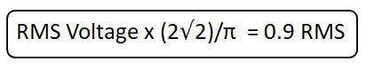
Thus
for an AC supply of say 220
volts the effective DC voltage will be 220 x 0.9 = 200 volts (approx.),
So, resistance per turn = (200/3,800) = 0.053 ohms. (This will apply to all lengths of machines!)
Amazing, you now know the essentials of designing a Magnabend coil !
It remains to find a wire thickness which "fits the bill", that is a wire which has a resistance of 0.053 ohms for 1 turn on our particular coil. Actually we need to find the average length of a turn:
For a core length of say 650mm and a coil depth of 19mm (as shown in the cross section above) then from straight forward geometry we find that the length of an average turn will be : (650 x 2) + (44 x Pi) = 1440 mm.
So we need a wire that has a resistance of 0.053 ohms per 1440 mm, that is a resistance of (0.053/1.440) ohms per metre,
that is = 0.0368 ohms per metre, or 36.8 ohms per Km.
From here you could calculate the actual diameter of the copper wire but you would need to know the conductivity of copper, which is not hard to find, but in practice what you now do is just lookup a table of information for various diameters of wire. (It has all been calculated before).
| Gauge AWG |
Wire Diameter mm |
Turns
of wire per cm |
Cross section mm2 |
Copper resistance ohms/Km |
| 15 | 1.45 | 6.9 | 1.65 | 10.5 |
| 16 | 1.29 | 7.7 | 1.31 | 13.2 |
| 17 | 1.15 | 8.7 | 1.04 | 16.6 |
| 18 | 1.024 | 9.77 | 0.823 | 21.0 |
| 19 | 0.912 | 11 | 0.653 | 26.4 |
| 20 | 0.812 | 12.3 | 0.518 | 33.3 |
| 21 | 0.723 | 13.8 | 0.41 | 42.0 |
| 22 | 0.644 | 15.5 | 0.326 | 53.0 |
| 23 | 0.573 | 17.4 | 0.258 | 66.8 |
| 24 | 0.511 | 19.6 | 0.205 | 84.2 |
The nearest wire size available in the table is 20 AWG so choose this one.
Now it is well worth noting that the cross-sectional area of 23 AWG is almost exactly half of the cross-sectional area of 20 AWG so that 2 strands of 23 gauge will give exactly the same effect (and occupy the same overall area) as 1 strand of 20 gauge.
That means you can use either size, but if you use 23 gauge you will need to join the strands together at the start (and at the end) and then wind with 2 strands in hand. This is called bi-filar winding. In fact you can use any combination of wire sizes that you like provided they add up to the correct cross-sectional area (0.518 mm2).
If you follow the above procedure for a 110 volt AC supply then you will find that the size of wire needed will be 17 AWG (or a bi-filar winding using 20 AWG).
We now know what size wire to use and this is the most important parameter of coil design. But we now have to actually make the coil.
How Many Turns?
The calculation below assumes that you know the area of the winding space, and you do know this if you are following my suggested cross section above. However if you were starting from scratch you would perhaps have to wind a test coil first and then measure how hot it gets when run at the desired duty cycle in the intended magnet body. If it gets too hot then that means that you need more turns and hence a larger winding space.Anyway, the number of turns will just be whatever will fit in the space available. This can be calculated from the known packing fraction.
For a jumble-wound coil with electrical paper all around it, the effective packing fraction is around 55%. This means that the space available will be 55% occupied by copper.
So, number of turns = 0.55 x (area of winding space)/ (area of 1 strand of wire). =[0.55 x 24 x 19)/0.518] = 484 turns.
Resistance of the Coil:
The resistance can be easily calculated by multiplying the number of turns by the resistance per turn (which was calculated above).Thus resistance = 484 x 0.053 ohms = 25.6 ohms (Note that this will be the resistance at room temperature, 20C. At higher temperatures the resistance will be higher).
Current:
The current will just be the effective DC coil voltage (0.9 x AC RMS voltage) divided by the resistance calculated above:Current = 220 x 0.9 ÷ 25.6 = 7.7 amps.
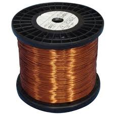
Type of Winding Wire to Use:
Normal magnet winding wire is copper wire coated with a polyester enamel, eg "PEI". However, for the Magnabend coil, it is highly desirable to obtain "self-bonding wire". This wire has an extra coat of a thermo setting material which, under heat, will melt and then cure thus binding all the windings in the coil together. If this wire cannot be obtained then it will be necessary to apply some other form of bonding agent (eg varnish) during the winding of the coil. (It is important that the windings are glued together otherwise the wires will vibrate and eventually wear themselves out).The Coil Former:
It is usual to make a former into which to wind the coil. The coil is later taken out of the former and put into the magnet.Make up a former looking something like this:
 Hold
the assembly together with several thru-bolts.
Hold
the assembly together with several thru-bolts.Make a hole in the centre thru which an axle can be inserted.
Line the winding space with electrical paper. This paper is typically about 0.3mm thick and its function is to insulate the coil from the metal poles of the magnet. (It is not safe to rely on the enamel insulation on the wire itself for this purpose).
Score the paper to make it fold in the right places.
You will probably need to temporarily tape the paper to the former to keep it out of the way during winding.
The dimensions of the coil former should be such that the coil which it forms will have clearance when it is installed in the magnet body.
The core piece of the former could be the same piece that will be used in the actual magnet. This will save the need to remove the coil from the core and then re-fit it to another core piece.
Also, have a look at notes about the coil under E-type magnet below.
Here is a comparison of electrical papers that you could use:
ELECTRICAL PAPERS:
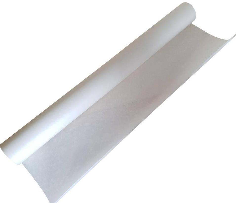 |
For example:Nomex 410 Insulation Paper - 0.25mm thick x 914mm wideApprox $35 per metre from www.swiftsupplies.com.au. |
| Description | Thickness | Tear Resistance | Puncture Resistance (Crossed Wire Test) | Moisture Immunity | Continuous Temperature Rating | Intermittent Temperature Rating |
| Hyply 10 + 3 | 0.31 mm | Good | Good | Moderate | ||
| Presspahn | 0.38 mm | Moderate | Very Good | Poor | 130 °C | 210 °C |
| DMD | 0.28 mm | Very Good | Moderate | Very Good | 155 °C | 235 °C |
| DMD | 0.40 mm | Very Good | Moderate | Very Good | 155 °C | 235 °C |
| Nomex 410 | 0.25 mm | Good | Good | Very Good | 220 °C | 300 °C |
I would recommend Nomex if you can obtain it easily, but any of those shown would be OK.
ALTERNATIVE INSULATION
FOR THE COIL:
Electrical paper might be difficult to obtain in an apprpropriate form, for example a small roll.
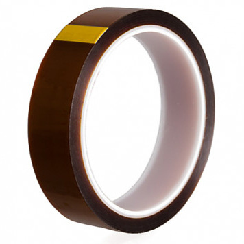
In that case you could consider insulating the coil with high temperature polyimide (Kapton) tape. This can be obtained from an electrical supplier such as RS Components or Element14 or even on eBay.
If using this method you would first form the coil (including the heat bonding stage) and then remove it from the former before wrapping it with the Kapton tape.
Tape dimensions: 33m x 19mm x .07mm, colour: amber, Temperature: up to 270 C
(Eg. RS Components number 468-403).
Electrical paper might be difficult to obtain in an apprpropriate form, for example a small roll.
In that case you could consider insulating the coil with high temperature polyimide (Kapton) tape. This can be obtained from an electrical supplier such as RS Components or Element14 or even on eBay.
If using this method you would first form the coil (including the heat bonding stage) and then remove it from the former before wrapping it with the Kapton tape.
Tape dimensions: 33m x 19mm x .07mm, colour: amber, Temperature: up to 270 C
(Eg. RS Components number 468-403).
Layer Winding versus Jumble Winding:
Layer winding is where the coil is wound in neat layers, usually with electrical paper between the layers. This method makes for a high quality coil but it is tedious and it is not really necessary for the Magnabend coil. The alternative to layer winding is "jumble winding" where the wires wind in in a fairly random fashion. It is however worth building up the coil in an even way. In particular you can avoid too much voltage difference between adjacent windings by making sure that outer windings do not come into contact with inner windings. (This will make it less likely to get insulation breakdown within the coil).Dispensing of the Winding Wire and Wire Tension:
 Winding
wire is normally supplied on a plastic spool. When dispensing
the
wire do not try to rotate the spool, rather just sit it
vertically on the floor (or in an old drum is better) and withdraw the
wire axially,
preferably thru
some kind of tensioning device mounted vertically above the spool. This
could just be a welding clamp fastened to something (eg a
table,
a bench etc ) with felt wrapped around the jaws to provide some
friction, and therefore tension to the wire. (Don't use anything that
would scratch the varnish insulation on the wire).
Winding
wire is normally supplied on a plastic spool. When dispensing
the
wire do not try to rotate the spool, rather just sit it
vertically on the floor (or in an old drum is better) and withdraw the
wire axially,
preferably thru
some kind of tensioning device mounted vertically above the spool. This
could just be a welding clamp fastened to something (eg a
table,
a bench etc ) with felt wrapped around the jaws to provide some
friction, and therefore tension to the wire. (Don't use anything that
would scratch the varnish insulation on the wire).Terminating the Coil:
It is best to provide the coil with flexible lead wires which are joined to the winding wire inside the coil.Since part of the lead wire will be inside the coil then it is best to use wire with teflon (or other high temperature) insulation.
Make the termination by soldering the flexible wire to the winding wire and then insulating the joint with heatshrink sleeving.
Use say a black wire at the start (inside) of the coil and a red wire for the end (outside) of the coil.
You will need to thoroughly scrape off the enamel coating from the winding wire before attempting to solder it.
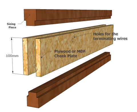
The terminating wires will be brought out through a pair of holes in one of the cheek plates.
Actual Winding of the Coil:
For a one-off coil it is not worth setting up an electric drive to turn the coil former. Just mount it on an axle and turn it by hand; it does not take all that long to put in the required number of turns (484, or even less if you are making a longer coil). (If you do want to set up an electric drive make it rotate the assembly fairly slowly, say about 50 RPM and control it with a foot-switch). The number of turns does not have to be precise. If you don't have an easy way of counting the turns (or if you loose count) then just monitor the total resistance. When it reaches about 25 ohms you can stop winding.Clamping the Coil to Size:
Because of the long nature of the Magnabend coil the
strands of wire between the ends remain quite loose unless they are
clamped up prior to curing the coil. You need to make up some ?sizing
pieces? as shown below. These can be made out of wood or some other
suitable material. (We used aluminium extrusion sections for production
coils).
It is best to have a short pair of pieces for the ends as well.
It is best to have a short pair of pieces for the ends as well.
You will need to calculate the dimensions
of the rebates in the sizing pieces such that when the
coil gets clamped up it will be the correct size to fit in your magnet
body.
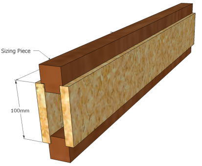
After the coil has been wound and the terminating
wires have been soldered on and brought out thru holes in the coil
former cheek plate, fold the edges of the electrical papers in and
install the sizing pieces. Apply 3 or 4 G-clamps to hold the sizing
pieces in place and screw up the G-clamps until the sizing pieces are
seated on their rebates all the way along.
Coil Curing:
Assuming that you have used self-bonding wire then curing involves heating the wire up to a temperature recommended by the manufacturer. Typically this will be something like 190 degrees C. The easiest way to do this is to connect the coil to a voltage source, via a rectifier, and let it self-heat. The temperature within the coil will be more uniform if the heating happens quickly, so it is preferable to use a higher than normal voltage for this. But even the standard supply voltage will still get the coil hot enough because it was designed for only 25% duty cycle so 100% duty will eventually get it pretty hot, especially when the coil is not installed in a steel magnet body.Now, how do you know when it is hot enough? Well fortunately the wire has a kind of built-in temperature gauge - its resistance increases with temperature in a very predictable way, so all you have to do is to monitor the current and when it has fallen to a certain value then the coil will be hot enough. At 190 C the current will have fallen to 60% of its starting value (room temperature value).
If you can't measure the current then instead you could disconnect the coil and measure its resistance at intervals. When the resistance has increased to 1.7 times the initial value then it will be hot enough).
(The value of 60% mentioned above may have to modified if the wire manufacturer has recommended a curing temperature much different to 190 C).
Mathematically the variation of resistance with temperature is expressed by:
(Where alpha is the coefficient of resistance, which for copper is 0.004/degree C)
You can easily substitute values into this formula. Note that T must be expressed in degrees C or K, but not degrees F.
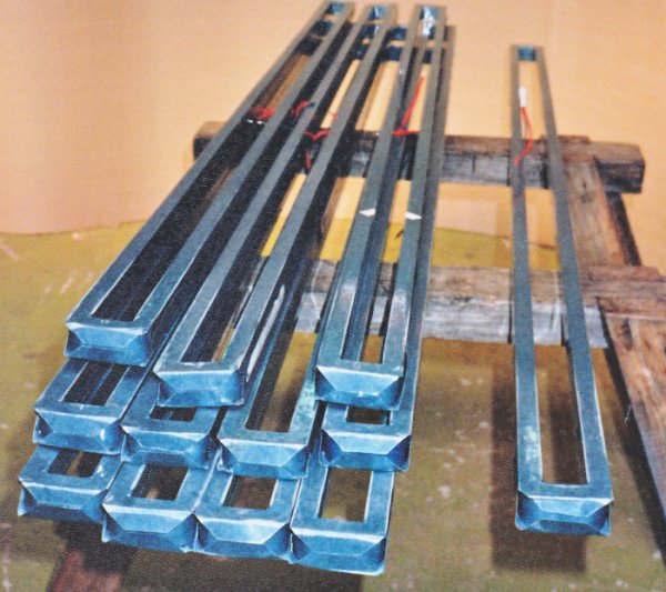
After winding, compressing to size, curing and removing from the former, Magnabend coils will look something like this:
Check your Coil Design here:
Coil Calculation Program (added August 2020)
Electrical Circuit for a Hobby Magnabend:
For simplicity you could consider using the minimal circuit:
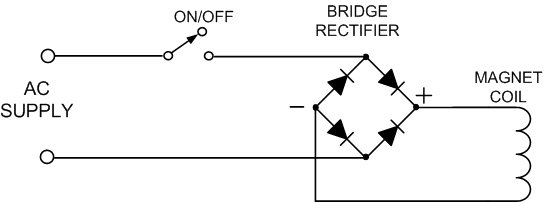
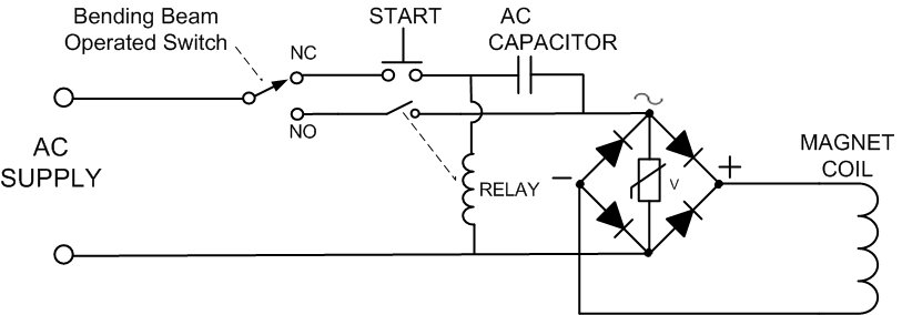
But practically you should go for a circuit with at least a 2-handed interlock and a light clamping phase such as shown below:
BRIDGE RECTIFIER:
The bridge rectifier converts the AC mains into DC for the magnet coil. The rectifier needs to have a current rating equal to or greater than the magnet coil current and a reverse voltage rating equal to or greater than the peak mains voltage. However, for improved reliability it is best to choose a rectifier which exceeds the minimum requirements by a generous margin.
A suitable rectifier would be:
RS Components part number: 227-8794
Max current: 35 amps continuous,
Max reverse voltage: 1000 Volts,
Terminals: 1/4" quick-connect or 'Faston'
Approx price: $14
DIODES:
If you are building a more advanced circuit then you will require several diodes. These can all be 1N5408.
Suitable diodes would be:
RS Components part number: 628-9473
Max current: 3 amps continuous,
Max reverse voltage: 1,000 Volts.
Approx price: $0.60 ($6.00 per pack of 10).
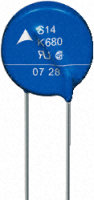
VARISTOR:
As the bridge rectifier is 'exposed' to the AC mains then it is susceptible to damage from voltage spikes. (Spikes are momentary large increases in voltage which sometimes occur on the mains which relate to sudden events such as truck running into a power pole, a lightning strike etc). To guard against this possibility it is good idea to fit a MOV ('varistor') across the ac terminals of the rectifier. The varistor should have a clamping voltage higher than the normal peak mains voltage but lower than the voltage rating of the rectifier.
 A
suitable
varistor
would be:
A
suitable
varistor
would be:Metal Oxide Varistor 500pF, RS part number 800-7059
Clamps at: 650 volts,
Clamping current: 50 amps,
Energy absorption: up to 72 joules,
Diameter: 17mm,
Approx price: $1.00.
THERMAL SWITCH:
As the Magnabend design is rated for only intermittent operation then the coil could be overheated if somehow the machine was to be left continuously ON by accident. To guard against this happening it is advisable to fit a bi-metallic switch to sense the temperature of the magnet body and to cut the current off it it gets too hot.
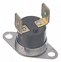
A suitable switch is:
Snap-acting bi-metallic switch,
RS Components part number 339-308
Rated at 240V ac, 10 amps.
Switch goes open circuit above 70°C, auto-resets to closed below 55°C
Terminals: 1/4" quick-connect.
Approx price: $15
This switch should be mounted (by 2 screws) somewhere to the base of the magnet body.
MICROSWITCH:
The ON/OFF switch can be any switch with suitable ratings. However if you want to couple this switch to the motion of the bending beam, ie to turn ON when the beam starts to move up, then you will probably want to use a V3 microswitch. These switches have over-center snap-acting contacts and are highly suitable for this kind of application.
A suitable V3 switch would be:
RS part number: 472-8235
Current rating: 16 amps
Voltage rating: 250 Volts AC
Lever type: long
Operating force: 0.91 Newton,
Terminals: 1/4" quick-connect
Approx price: $5.00
RELAY:
If you automate the turn-on with a V3 switch, as above, then it is strongly advised that you also incorporate the additional circuitry required to give a 2-handed interlock (otherwise it is all too easy to accidentally turn the magnet on and possibly cause an accident).
It is possible to do a 2-handed interlock circuit without the need for a relay but it would require that a button (the Start button) be held in continuously whilst doing a bend. It is much more convenient if the Start button only has to be pressed to initiate the interlock and in that case a relay will be required.
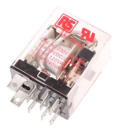
A suitable relay would be:
RS part number: 450-0380
Switching capacity: 10 amp, 240 volt ac,
Coil: 240 volt ac,
Contact arrangement: DPDT,
Approx price: $10.00
The relay shown here has 2 poles. This provides for the possibility that you may also want to implement a demagnetising circuit as well, but if not then the second pole can be ignored or you can choose a single pole relay which would be slightly cheaper.
LIGHT-CLAMPING CAPACITOR:
To achieve a 2-handed interlock circuit with a pre-clamping phase you will need a capacitor rated for continuous operation on the AC mains. The best type to use are ones designed for power factor correction (eg in fluorescent lights)., and these may be referred to as 'lighting capacitors'.
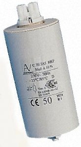 |
A suitable
capacitor : RS Components part number: 451-5411 Capacitance:10 µF Voltage rating: 250 VAC continuous, Mounting: M8 stud, Diameter: 35mm Approx price: $15.00 |
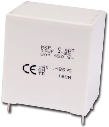 |
Alternative
capacitor: RS Components part number: 123-5095 Capacitance: 10 µF Voltage rating: 250 VAC continuous, Dimensions: 41 x 40 x 20 mm Approx price: $9 |
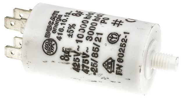
Another alternative is this "motor-run" capacitor.
This device has the advantage of quick connect terminals.
RS part number: 388-7967
Capacitance: 8 µF, Voltage rating: 450 VAC continuous,
Mounting: M8 stud.
Diameter : 30mm , Height: 55mm.
Approx price: $7.00 (May 2020).
Please also consult the section: Magnabend Circuit Operation for other ideas and more advanced circuits.
The E-Type magnet cross section achieves a higher clamping force from a given weight of steel and copper wire. If you have good milling facilities at your disposal then this is the design to go for.
This design assumes that the magnet body will be machined from a hot-rolled steel blank 100 x 50 mm. The dimensions allow for machining the blank on all sides to clean up the mill scale and remove a minor amount of lack of straightness. If you are making a long magnet then it is quite likely that some pre-straightening will be required prior to machining. (See below).
If the blank can be obtained as a cold-rolled section then clean-up machining may not be required and hence the above outer dimensions could be increased to match the size of the blank.
Length:
You can make the length pretty much anything you like. This same section has been used for Magnabends up to 3.2 meters long. However, you should note the relative dimensions between the coil and the magnet body. For instance the coil is longer than the steel 'island' that it has to fit over but it is narrower than the channels that it has to fit into. It needs to have clearance - it would be very disappointing to have gone to the trouble of making a nice coil only to find that it will not fit into the space available in the magnet body!Note that you will only get full clamping force to within about 50mm of each end. This is because the flux concentration near the ends gets considerably reduced by fringing into the (longer) outer poles. This has a more severe effect than might be expected.
Material:
A medium carbon steel, say K1045, is a good choice however if you cannot obtain this then CS1020 would be OK or just mild steel is also OK but it will damage a bit more easily and does not machine quite as well as the higher carbon steels.Construction:
Machining from a solid steel blank will produce the best result both physically and magnetically. However it is also possible to produce the E-Type body by fabrication.For details on a fabricated construction please follow this link:
http://aaybee.com.au/Magnabend/Handyman_Pages/Magnet-Body.html
Straightening:
"As-supplied" hot-rolled steel blanks are hardly ever straight enough to be machined without some prior straightening. This particularly applies to longer lengths.If a bent piece of steel is pressed until it is straight it will retain some internal stress and that stress may cause it to creep over time and relax back into a slightly bent condition again .
To overcome this behaviour a stabilised straightening technique can be used. This is described below.
The general principle of stabilised bending is to “ring” the bend. That means to successively bend the material to and fro but with each bend progressively reduced in amplitude until no further yielding results.
 "Ringing"
is the term often applied to a
decaying oscillation such as shown on the left.
"Ringing"
is the term often applied to a
decaying oscillation such as shown on the left.When applied to bending this technique will leave the material in the vicinity of the bend in a stress-free condition. The material will then be stable and not subject to creep.
In principle the method is a substitute for stress relieving by heating although for complete stress relief the bar to be straightened would need to be worked on from end to end.
Typically 3 oscillations of the bend will produce sufficient stability for our purposes.
PROCEDURE:
- Locate the worst hump or hollow in the workpiece by using a straight-edge.
- Using a workshop press of sufficient capacity (20 tons is sufficient for Magnabend sections) press the hump with sufficient pressure to cause it to be slightly bent the other way (i.e. over compensated). Check with a straight edge and if necessary, press again with a slightly increased force until over-compensation is achieved.
- Turn the workpiece over and press the other way to half the initial force.
- Turn the workpiece back to the original orientation and press to quarter the initial force.
- Check the overall straightness and if
it is not straight enough, repeat from step 1.
Maximum deviation from the straight-edge should be within specifications. (Magnetic Engineering specification was 0.2mm max.)
NOTE:
In a production situation a table of pressing forces should be established to show the forces required to yield different workpieces (clamp bars, magnet bodies, bending beams, etc) and according to workpiece support spacings etc.
Mechanics:
It is a good idea to drill and tap the magnet body for the various fasteners required before installing the coil. That way you minimise the danger of drilling into the coil which would probably effectively destroy it. You need to think about fasteners for the hinges, an electrical enclosure, back-stop bars (if required), a utility tray, some kind of stand etc.The Coil:
The coil will be made much the same way as for the U-type body as described above except that the terminating wires need to come out on the bottom face of the coil and would then pass thru a hole in the base of the body to join up with the electrical circuit.Before installing the coil make absolutely sure that there are no sharp burrs or swarf that might puncture thru the coil insulation. Pay particular attention to ends of the central pole; file the sharp edges off and make everything clean. Provided the insulation remains sound then the coil should last pretty much forever. (You want it to last a long time because it is very difficult to replace later if it does fail).
Protection for the Coil:
Commercial Magnabends protect the coil with aluminium strips (20 x 3 mm) which are supported in small rebates milled into the poles. These are peened after installation to produce a jamming fit and then the surface of the magnet body is given a final light machining.However for a hobby Magnabend I am going to suggest another method which involves less machining:
Just fill up the space above (and at the end of) the coil with a polyester resin such as body filler. A typical brand being K&H (in Australia) or Bondo (a popular brand in the US). This material is thixotropic, meaning that it will stay in place and does not run out (like honey would). Also it has good heat resistance and is not particularly expensive.
After the resin has cured (about half an hour depending on the temperature and the amount of catalyst added to the mix), it can be sanded nice and flush with the steel surface using a belt sander.
Contact Alan Magnabend Homepage Alan's Homepage
| This page last updated 16 October 2020 |