Contact Alan Magnabend Homepage Alan's Homepage
| MAGNABEND - CIRCUIT OPERATION |
The Magnabend sheetmetal folder is designed as a DC clamping electromagnet.
The simplest circuit required to drive the electro-magnetic coil consists of a switch and a bridge rectifier only:
Figure 1: Minimal Circuit:
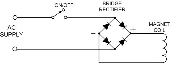
It is to be noted that the ON/OFF switch is connected on the AC side of the circuit. This allows the inductive coil current to circulate through the diodes in the bridge rectifier following turn-off until the current decays exponentially to zero.
(The diodes in the bridge are acting as "fly-back" diodes).
For safer and more convenient operation it is desirable to have a circuit which provides a 2-handed interlock and also 2-stage clamping. The 2-handed interlock helps to ensure that fingers cannot be caught under the clampbar and the staged clamping gives a softer start and also allows one hand to hold things in place until the pre-clamping is activated.
Figure 2: Circuit with Interlock and 2-Stage Clamping:
When the START button is pressed a small voltage is supplied to the magnet coil via the AC capacitor thus producing a light clamping effect. This reactive method of limiting the current to the coil involves no significant power dissipation in the limiting device (the capacitor).
Full clamping is obtained when both the Bending Beam-operated switch and the START button are operated together.
Typically the START button would be pushed first (with the left hand) and then the handle of the bending beam would be pulled with the other hand. Full clamping will not occur unless there is some overlap in the operation of the 2 switches. However once full clamping is established it is not necessary to keep holding the START button.
Residual Magnetism
A small but significant problem with the Magnabend machine, as with most electro-magnets, is the problem of residual magnetism. This is the small amount of magnetism that remains after the magnet is turned OFF. It causes the clamp-bars to remain weakly clamped to the magnet body thus making removal of the workpiece difficult.Use of magnetically soft iron is one of many possible approaches to overcoming residual magnetism.
However this material is hard to obtain in stock sizes and also it is physically soft which means that it would be easily damaged in a bending machine.
The inclusion of a non-magnetic gap in the magnetic circuit is perhaps the simplest way to reduce remnant magnetism. This method is effective and is fairly easy to achieve in a fabricated magnet body - just incorporate a piece of cardboard or aluminium about 0.2mm thick between say the front pole and the core piece before bolting the magnet parts together. The main drawback of this method is that the non-magnetic gap does reduce the flux available for full clamping. Also it is not straight forward to incorporate the gap in a one-piece magnet body as used for the E-type magnet design.
A reverse bias field, produced by an auxiliary coil, is also an effective method. But it involves unwarranted extra complexity in the manufacture of the coil and also in the control circuitry, although it was used briefly in an early Magnabend design.
A decaying oscillation ("ringing") is conceptually a very good method for demagnetising.
These oscilloscope photos depict the voltage (top trace) and current (bottom trace) in a Magnabend coil with a suitable capacitor connected across it to make it self oscillate. (The AC supply has been turned off approximately in the middle of the picture).
The first picture is for an open magnetic circuit, that is with no clampbar on the magnet. The second picture is for a closed magnetic circuit, that is with a full length clampbar on the magnet.
In the first picture the voltage exhibits decaying oscillation (ringing) and so does the current (lower trace), but in the second picture the voltage does not oscillate and the current does not even manage to reverse at all. This means that there would be no oscillation of the magnetic flux and hence no cancellation of residual magnetism.
The problem is that the magnet is too heavily damped, mainly due to eddy current losses in the steel, and thus unfortunately this method does not work for the Magnabend.
Forced oscillation is yet another idea. If the magnet is too damped to self-oscillate then it could be forced to oscillate by active circuits supplying energy as required. This has also been thoroughly investigated for the Magnabend. Its main drawback is that it involves overly complicated circuitry.
Reverse-pulse demagnetising is the method which has proved most cost-effective for the Magnabend. The details of this design represent original work performed by Magnetic Engineering Pty Ltd. A detailed discussion follows:
REVERSE-PULSE DEMAGNETISING
A further advantage of the reverse-pulse method is that it produces very fast demagnetising and an almost instant release of the clampbar from the magnet. This is because it is not necessary to wait for the coil current to decay to zero before connecting the reverse pulse. On application of the pulse the coil current is forced to zero (and then into reverse) very much faster than its normal exponential decay would have been.
Figure 3: Basic Reverse-Pulse Circuit

Now, normally, placing a switch contact between the rectifier and the magnet coil is "playing with fire".
This is because an inductive current cannot be suddenly interrupted. If it is then the switch contacts will arc and the switch will be damaged or even completely destroyed. (The mechanical equivalent would be trying to suddenly stop a flywheel).
Thus, whatever circuit is devised it must provide an effective pathway for the coil current at all times, including for the few milliseconds while a switch contact changes over..
The above circuit, which consists of only 2 capacitors and 2 diodes (plus a relay contact), achieves the functions of charging the Storage capacitor to a negative voltage (relative to the reference side of the coil) and also provides an alternative pathway for coil current while the relay contact is on the fly.
How it works:
Broadly D1 and C2 act as a charge pump for C1 while D2 is a clamp diode which holds point B from going positive.
While the magnet is ON the relay contact will be connected to its "normally open" (NO) terminal and the magnet will be doing its normal job of clamping sheetmetal. The charge pump will be charging C1 towards a peak negative voltage equal in magnitude to the peak coil voltage. The voltage on C1 will increase exponentially but it will be fully charged within about 1/2 a second.
It then remains in that state until the machine is turned OFF.
Immediately after switch-off the relay holds in for a short time. During this time the highly inductive coil current will continue to recirculate thru the diodes in the bridge rectifier. Now, after a delay of about 30 milliseconds the relay contact will start to separate. The coil current can no longer go thru the rectifier diodes but instead finds a path thru C1, D1, and C2. The direction of this current is such that it will further increase the negative charge on C1 and it will begin to charge C2 also.
The value of C2 needs to be large enough to control the rate of voltage rise across the opening relay contact to ensure that an arc does not form. A value of about 5 micro-farads per amp of coil current is adequate for a typical relay.
Figure 4 below shows details of the waveforms which occur during the first half a second after turn OFF. The voltage ramp which is being controlled by C2 is clearly visible on the red trace in the middle of the figure, it is labeled "Relay contact on the fly". (The actual fly-over time can be deduced from this trace; it is about 1.5 ms).
As soon as the relay armature lands on its NC terminal the negatively charged storage capacitor is connected to the magnet coil. This does not immediately reverse the coil current but the current is now running "uphill" and thus it is quickly forced thru zero and towards a negative peak which occurs about 80 ms after the connection of the storage capacitor. (See Figure 5). The negative current will induce a negative flux in the magnet which will cancel out the residual magnetism and the clampbar and workpiece will be quickly released.
Figure 4: Expanded Waveforms
Figure 5: Voltage and Current Waveforms on Magnet Coil
Figure 5 above depicts the voltage and current waveforms on the magnet coil during the pre-clamping phase, the full clamping phase, and the demagnetising phase.
It is thought that the simplicity and effectiveness of this demagnetising circuit should mean that it will find application in other electromagnets that need demagnetising. Even if residual magnetism is not a problem this circuit could still be very useful to commutate the coil current to zero very quickly and hence give rapid release.
Practical Magnabend Circuit:
The circuit concepts discussed above can be combined into a full circuit with both a 2-handed interlock and reverse pulse demagnetising as shown below (Figure 6):
Figure 6: Combined Circuit
This circuit will work but unfortunately it is somewhat unreliable.
To obtain reliable operation and longer switch life it is necessary to add some extra components to the basic circuit as shown below (Figure 7):
Figure 7: Combined Circuit with Refinements
SW1:
This is a 2-pole isolating switch. It is added for convenience and to comply with electrical standards. It is also desirable for this switch to incorporate a neon indicator light to show the ON/OFF status of the circuit.
D3 and C4:
Without D3 the latching of the relay is unreliable and depends somewhat on the phasing of the mains waveform at the time of operation of the bending beam switch. D3 introduces a delay (typically 30 milli seconds) in the drop out of the relay. This overcomes the latching problem and it is also beneficial to have a drop out delay just prior to the onset of the demagnetising pulse (later in the cycle). C4 provides AC coupling of the relay circuit which would otherwise be a half-wave short circuit when the START button was pressed.
THERM. SWITCH:
This switch has its housing in contact with the magnet body and it will go open circuit if the magnet gets too hot (>70 C). Putting it in series with the relay coil means that it only has to switch the small current through the relay coil rather than the full magnet current.
R2:
When the START button is pressed the relay pulls in and then there will be an in-rush current which charges C3 via the bridge rectifier, C2 and diode D2. Without R2 there would be no resistance in this circuit and the resulting high current could damage the contacts in the START switch.
Also, there is another circuit condition where R2 provides protection: If the bending beam switch (SW2) moves from the NO terminal (where it would be carrying the full magnet current) to the NC terminal, then often an arc would form and if the START switch was still being held at this time then C3 would in effect be short circuited and, depending on how much voltage was on C3, then this could damage SW2. However again R2 would limit this short circuit current to a safe value. R2 needs only a low resistance value (typically 2 ohms) in order to provide sufficient protection.
Varistor:
The varistor, which is connected between the AC terminals of the rectifier, normally does nothing. But if there is a surge voltage on the mains (due to for instance - a nearby lightening strike ) then the varistor will absorb the energy in the surge and prevent the voltage spike from damaging the bridge rectifier.
R1:
If the START button was to be pressed during a demagnetising pulse then this would likely cause an arc at the relay contact which in turn would virtually short-circuit C1 (the storage capacitor). The capacitor energy would be dumped into the circuit consisting of C1, the bridge rectifier and the arc in the relay. Without R1 there is very little resistance in this circuit and so the current would be very high and would be sufficient to weld the contacts in the relay. R1 provides protection in this (somewhat unusual) eventuality.
Special Note re Choice of R1:
If the eventuality described above does occur then R1 will absorb virtually all of the energy that was stored in C1 regardless of the actual value of R1. We want R1 to be large compared with other circuit resistances but small compared with the resistance of the Magnabend coil (otherwise R1 would reduce the effectiveness of the demagnetising pulse). A value of around 5 to 10 ohms would be suitable but what power rating should R1 have? What we really need to specify is the pulse power, or energy rating of the resistor. But this characteristic is not usually specified for power resistors. Low value power resistors are usually wire-wound and we have determined that the critical factor to look for in this resistor is the amount of actual wire used in its construction. You need to crack open a sample resistor and measure the gauge and the length of wire used. From this calculate the total volume of the wire and then choose a resistor with at least 20 mm3 of wire.
(For example a 6.8 ohm/11 watt resistor from RS Components was found to have a wire volume of 24mm3).
Fortunately these extra components are small in size and cost and hence add only a few dollars to the overall cost of the Magnabend electrics.
There is an additional bit of circuitry that has not yet been discussed. This overcomes a relatively minor problem:
If the START button is pressed and is not followed by pulling on the handle (which would otherwise give full clamping) then the storage capacitor will not be fully charged and the demagnetising pulse that results on release of the START button will not fully demagnetise the machine. The clampbar would then remain stuck to the machine and that would be a nuisance.
The addition of D4 and R3, shown in blue in Figure 8 below, feed a suitable waveform into the charge pump circuit to ensure that C1 gets charged even if full clamping is not applied. (The value of R3 is not critical - 220 ohms/10 watt would suit most machines).
Figure 8: Circuit with Demagnetise after "START" only:
For more information about circuit components please refer to the Components section in "Build Your Own Magnabend"
For reference purposes the full circuit diagrams of 240 Volt AC, E-Type Magnabend machines manufactured by Magnetic Engineering Pty Ltd are shown below.
Note that for operation on 115 VAC many component values would need to be modified.
Magnetic Engineering ceased production of Magnabend machines in 2003 when the business was sold.
Note: The above discussion was intended to explain the main principles of the circuit operation and not all details have been covered. The full circuits shown above are also included in the Magnabend manuals which are available elsewhere on this site.
It is also to be noted that we developed fully solid state versions of this circuit which used IGBTs instead of a relay to switch the current.
The solid state circuit was never used in any Magnabend machines but was used for special magnets that we manufactured for production lines. These production lines typically turned out 5,000 items (such as a refrigerator door) per day.
Magnetic Engineering ceased production of Magnabend machines in 2003 when the business was sold..
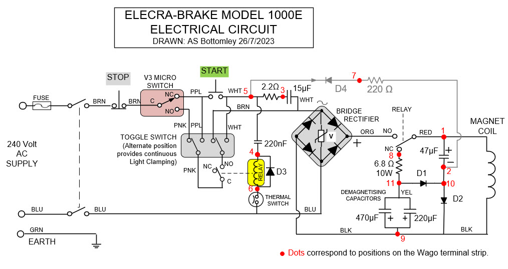
I recently helped someone who needed a circuit diagram of a Model 1000E "Electra Brake" brand Magnabend machine.
Figure 9: Electra Brake Model 1000E Electrical Circuit Diagram:
Please use the Contact Alan link on this site to seek more information.
Contact Alan Magnabend Homepage Alan's Homepage
| This page last updated: 19 September 2015 |