Contact Alan Magnabend Homepage Alan's Homepage
MAGNABEND ELECTROMAGNET DESIGN TOOL
I am indebted to my colleague, Mr Tony Grainger, for the JavaScript program which performs the calculations for this page.
Electromagnet Design Tool
The program on this page is a powerful aid for designing magnets for the "Magnabend" electromagnetic sheet metal bending machine.The program produces detailed Calculated Results, and also draws, in real time, the magnet cross section that corresponds with your typed-in Magnet Input Data.
calculator goes here
cross section goes here
How to use this page:
An electromagnet consists of 2 basic parts; an electric circuit (or coil) and a magnetic circuit (or flux path).
An electric current in the coil induces a magnetic current (flux) in the magnetic circuit.
The program on this page brings together all the salient features of both these basic parts and makes detailed calculations to inform your electromagnet design.
Feel free to experiment.
You can type any numbers you like into the input fields. The program will immediately make all the relevant calculations and present them in the "Calculated Results"section.
At the same time both the geometry and the dimensions for electromagnet cross section drawing will be automatically updated
.
Additional Calculated Results can be displayed if desired by clicking on the "Details +/-" button. These additional results will not usually be needed but may be useful for advanced designers.
To reset the program to the default numbers just refresh (or reload) this web page.
The calculations assume that the coil is made from copper wire (resistivity = 0.0171 Ωm at 20ºC) and that the magnet body is made from mild steel SAE 1020.
The relationship between the magnetisation in the steel and the field strength is non linear and cannot be represented by an equation.
The calculations on this page use a table lookup followed by an iterative method to obtain accurate results for the flux density pertaining to the particular magnet configuration.
MAGNETISATION DATA:
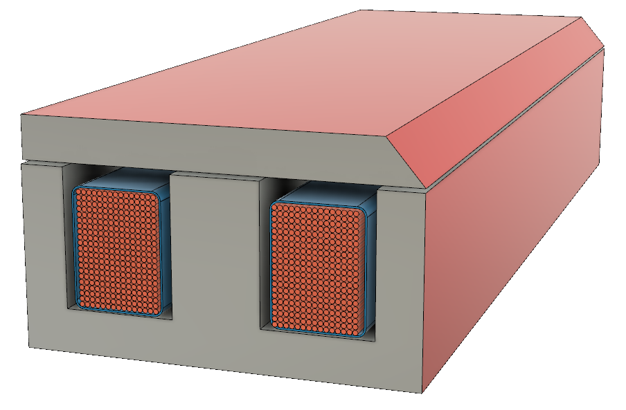
Magnet End Configurations:
Two common ways of finishing the end of a Magnabend magnet are shown below:
In the first picture the outer poles of the magnet are longer than the middle poles, and in the second picture all the poles are the same length. (The configuration in the second picture provides better clamping near the ends of the magnet).


When entering dimensions into the calculator above the effective magnet length is the length of the middle poles.
How Much Clamping Force is Needed?
The Electromagnet Design Tool at the the top of this page provides a means for calculating the clamping force obtainable from just about any magnet configuration, but it does not provide information about how much force is needed for a given bending job.
The bending force needed depends on:-
- The length of the bend, L
- The thickness of the sheet, t
- The tensile strength of the material, σ
- The width of the flange being bent, w.
- And the bend radius of the bend, r
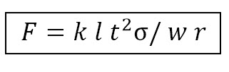
That unit can be divided by 9,810 to produce tones per metre which matches the unit for "Clamping per metre" in the calculator at the top of this page.
k is a dimensionless constant. By measuring values for a known marginal bend we can derive an empirical value for k that will apply to bending with a Magnabend. The value of k will be only approximate as the the bending force also depends on the tendency for the sheet material to work-harden during bending and on other factors such as the frictional value on the surface of the Magnabend.
Here is a handy table of wire sizes that will encompas most gauges that are likely to be needed for a magnet coil.
| Preferred wire diameters |
Wire cross
sectional area. |
Kg
per Km |
Nearest SWG gauge |
Nearest AWG gauge |
| 2.00 mm | 3.14 mm2 | 27.9 | 14 | 12 |
| 1.80 mm | 2.54 mm2 | 22.6 | 15 | 13 |
| 1.60mm | 2.01 mm2 | 17.9 | 16 | 14 |
| 1.40 mm | 1.54 mm2 | 13.7 | 17 | 15 |
| 1.25 mm | 1.23 mm2 | 10.9 | 18 | 16 |
| 1.12 mm | 0.985 mm2 | 8.76 | 19 | 17 |
| 1.00mm | 0.785mm2 | 6.98 | 19 | 18 |
| 0.90 mm | 0.636 mm2 | 5.66 | 20 | 19 |
| 0.80mm | 0.503 mm2 | 4.47 | 21 | 20 |
| 0.71 mm | 0.396 mm2 | 3.52 | 22 | 21 |
| 0.60 mm | 0.283 mm2 | 2.51 | 23 | 22 |
| 0.56 mm | 0.246 mm2 | 2.19 | 24 | 23 |
| 0.50 mm | 0.196mm2 | 1.75 | 25 | 24 |
| 0.45mm | 0.159 mm2 | 1.41 | 26 | 25 |
| 0.40mm | 0.126 mm2 | 1.12 | 27 | 26 |
| 0.37mm | 0.110mm2 | 0.98 | 28 | 27 |
See also the Coil Calculator.