| MAGNABEND HANDYMAN MODEL |

MOUNTING
THE HANDYMAN MACHINE
The Handyman machine can be bench-mounted (to an existing bench) or floor mounted via a stand.
1. Bench Mounting:
If you have enough spare bench space then bench-mounting is the cheapest and easiest way to install the machine.
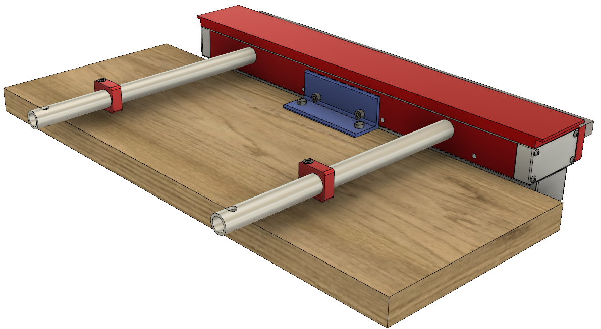
All that is needed for this is an angle bracket and some fasteners. (See the blue item in the drawing below).

The method shown here sets the machine a little above the the surface of the bench and thus allows the use of the backstop bars and backstop collars.
If you do not require the backstop bars then the machine could be mounted flush with the bench top.
In this case the exact method of mounting will depend on the nature and construction of the bench.
2. Floor Mounting:
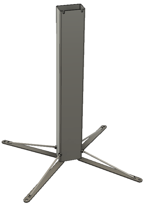
Floor mounting, via the single post stand shown below, allows the machine to be completely independent of any benches and provides for the maximum amount of free-arm effect around the ends of the machine.
 |
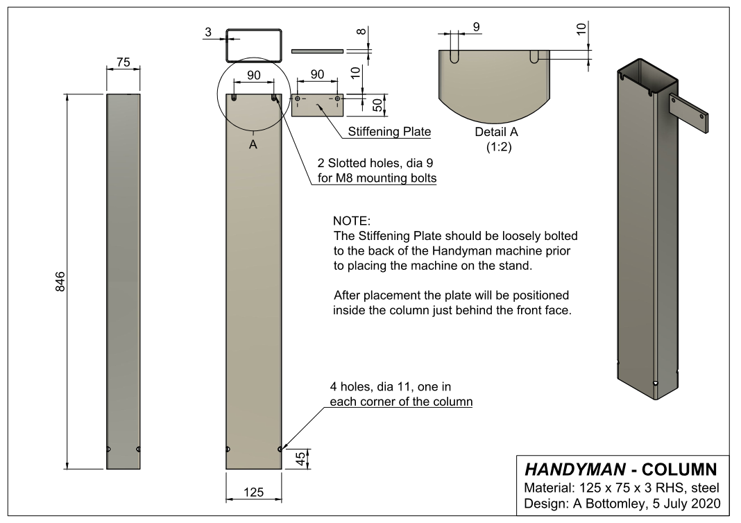
The stand consists of a column made from rectangular hollow section (RHS) and 4 special feet. The RHS dimensions are 125 x 75 x 3mm (wall thickness). The vertical length is 846mm. ( When mounted the machine will have a surface height of 900mm). Most steel suppliers will sell this section by-the-metre, so if you are making a one-off machine you do not need to purchase a whole length (which is usually 8m). This size RHS is also available with a thinner wall thickness of 2.0mm. That wall thickness is also suitable for this stand but is not a preferred stocking size for most steel suppliers. Cost for a 1 metre long piece of RHS will be about $30 (or about $20 if you can get the thinner wall version). |
The stand requires 4 feet, one on each corner. These feet have been specially designed such that no welding is required in their manufacture. They are very light weight and yet provide a very stiff connection to the column.

When mounted each foot points downwards (by 3 degrees) such that only the tip touches the floor. This gives the stand good stability. (The downward pointing angle is built into the design of the foot).
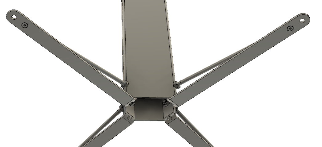
Only a single hole (one in each corner of the column) is required to mount each foot. No other fasteners are required.

The stand viewed from underneath.
When assembling a foot to the stand, insert the threaded rod into the
column before installing the M6 countersunk screw which fastens the end
of the rod. Finger-tighten the outer M10 nut on each rod and then
install, and loosly tighten, the 4 internal M10 nuts.Check if the stand sits on the floor without rocking. If one of the feet needs to point down more then further tighten its outer M10 nut. Finally firmly tighten all the internal M10 nuts.
FLOOR STAND - DRAWINGS
The drawings below are in draft form. If you register your interest then you will be notified whenever there is an update to any drawing.
1. COLUMN: Enlarged view. PDF drawing.

2. FOOT: (Click on drawing to enlarge):

"Handyman" Index page.
Contact Alan Magnabend Homepage Alan's Homepage
This
page last updated: 27 May 2021