| MAGNABEND HANDYMAN MODEL |

HEMI-HINGE
These hinges were developed for the "Handyman" magnetic folder as a simpler alternative to the centreless compound hinge described elsewhere on this website.
The "Hemi-Hinge" can be made, two-at-a-time, in an independent 4-jaw chuck on an ordinary lathe.
(Note: I have a modified design of the Hemi-Hinge which can be made in a self-centring 4-jaw chuck.
Please contact me if you want to make this design).
This hinge is centreless in the sense that the hinge parts are all on one side of the pivot axis. This allows the hinges to be placed anywhere along the bending beam and also results in a completely open-ended folding machine.
The Hemi-Hinge could also be utilised in other, non magnetic, folding machines.
It has a limited pivot angle of 115 degrees.
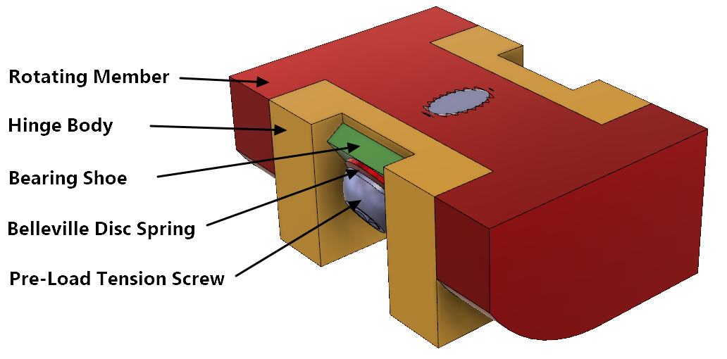
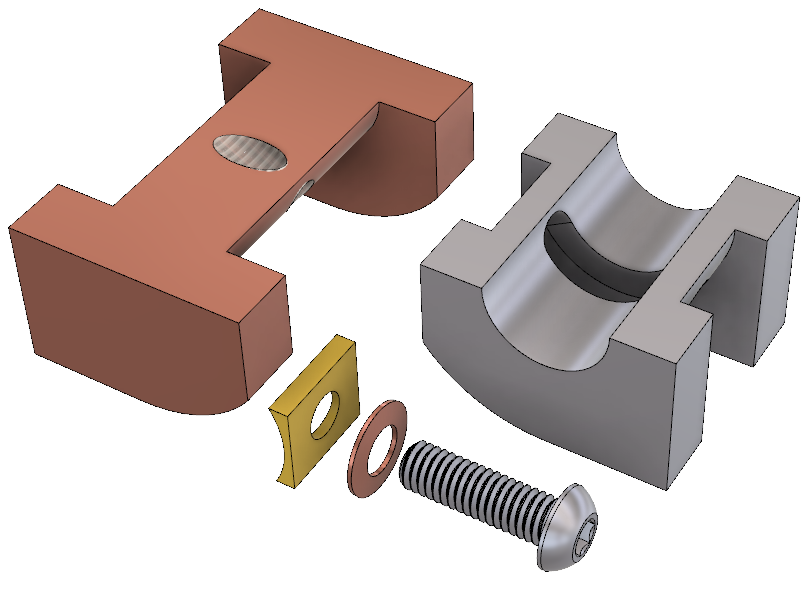
Hemi-Hinge Parts Identification
MANUFACTURING THE HEMI-HINGE
The procedure below assumes that you are making a single pair of hinges. If multiple hinges are being made then a different approach would probably be used.
Belleville washer specifications: 12.5 x 6.2 x 0.5mm (OD x ID x Thickness).
Preferably obtain alloy steel eg 60Si2Mn. Alloy steel has a better spring range than stainless steel.
A possible supplier for the Belleville washer: hkes-fastener.
HINGE BODY:
Click here for a larger view or click here for HINGE BODY.PDF

HINGE PIVOT MEMBER:
Click here for a larger view or click here for HINGE PIVOT.PDF

HINGE CLAMPING JIG:
Click here for a larger view or click here for HINGE CLAMPING JIG.PDF
"Handyman" Index page.
Contact Alan Magnabend Homepage Alan's Homepage
These hinges were developed for the "Handyman" magnetic folder as a simpler alternative to the centreless compound hinge described elsewhere on this website.
The "Hemi-Hinge" can be made, two-at-a-time, in an independent 4-jaw chuck on an ordinary lathe.
(Note: I have a modified design of the Hemi-Hinge which can be made in a self-centring 4-jaw chuck.
Please contact me if you want to make this design).
This hinge is centreless in the sense that the hinge parts are all on one side of the pivot axis. This allows the hinges to be placed anywhere along the bending beam and also results in a completely open-ended folding machine.
The Hemi-Hinge could also be utilised in other, non magnetic, folding machines.
It has a limited pivot angle of 115 degrees.
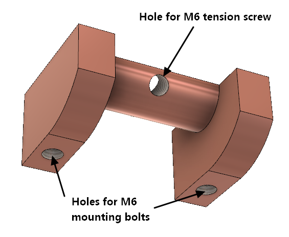
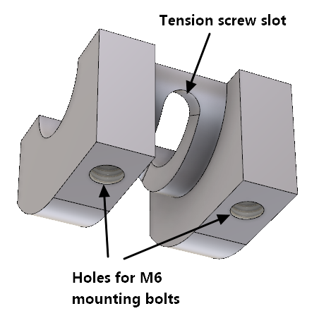
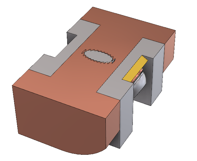
Hemi-Hinge Parts Identification

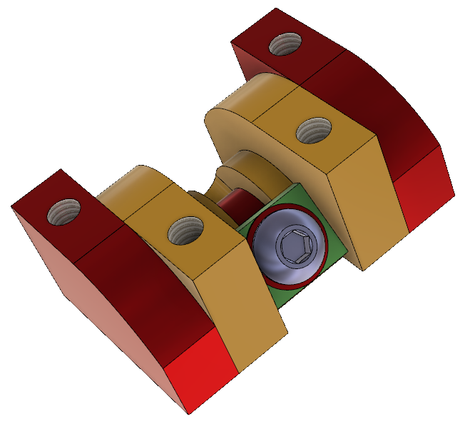 Hinge viewed from underneath |
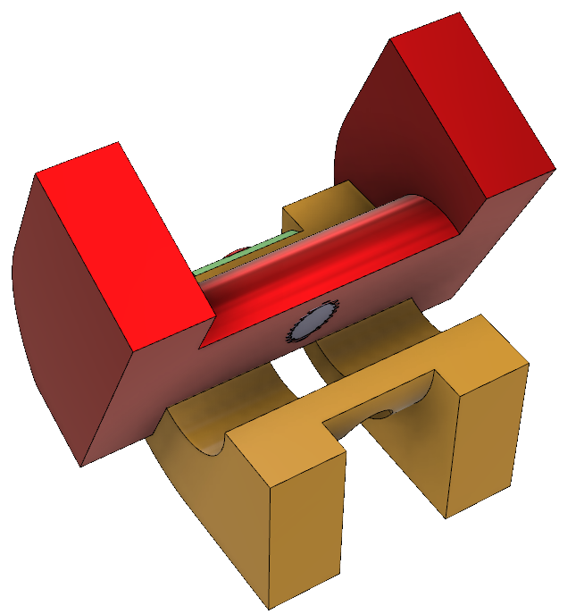 Hinge rotated to 115 degrees |
MANUFACTURING THE HEMI-HINGE
The procedure below assumes that you are making a single pair of hinges. If multiple hinges are being made then a different approach would probably be used.
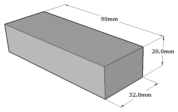
STEP 1 - Make the raw blocks. The Hemi-Hinge is made from mild steel bar with dimensions 32 x 20mm. This section size is available as a BMS bar, typically in grade M1020. Manufacturers should obtain this BMS bar but if only a single hinge-pair is being made then the blocks could be made by maching down a 32mm square bar, or alternatively cutting from a 20mm thick flat bar. If making from a flat bar the blocks should be cut a little oversize and then milled to obtain accurate sizes and parallel sides. |
 |
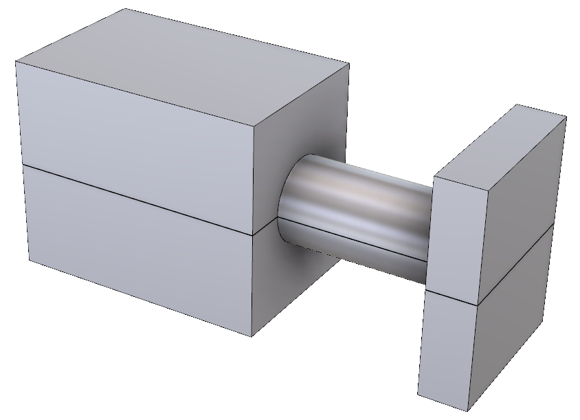
STEP 2 - Machine the Pivoting Member. Now place two hinge blocks one on top of the other and clamp them up in a 4-jaw lathe chuck. Adjust the jaws to get the workpiece accurately centered. (You will need a chuck with independant jaws). Clamp the blocks with 43mm of length projecting out from the chuck jaws. Take a light cut to face off the end. Using a suitable tool (such as a parting tool) machine the blocks as shown on the right. A steady should not be necessary. The cylindrical surface does not need to be polished but a smooth finish is desirable. |
 |
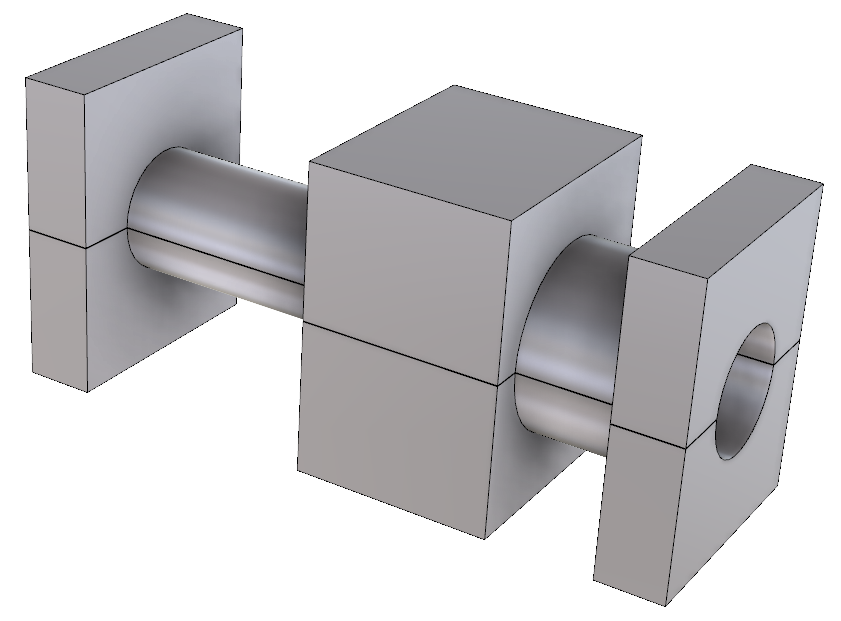
STEP 3 - Machine the Hinge Body. Next reverse the workpiece in the 4-jaw chuck and clamp up. Check that the centering is still true. As before leave 43mm of length projecting out from the chuck jaws and then machine as shown in the drawing. Next drill the central hole to 16mm diameter and 33mm deep. (If you are using a good machining steel then it should not be necessary to bore the central hole after dilling). This part also requires a radial slot. If a multi-axis lathe is available then it may be possible to make the slot in this same setup. Otherwise you could use a rotary milling table or see STEP 6 below. |
 |
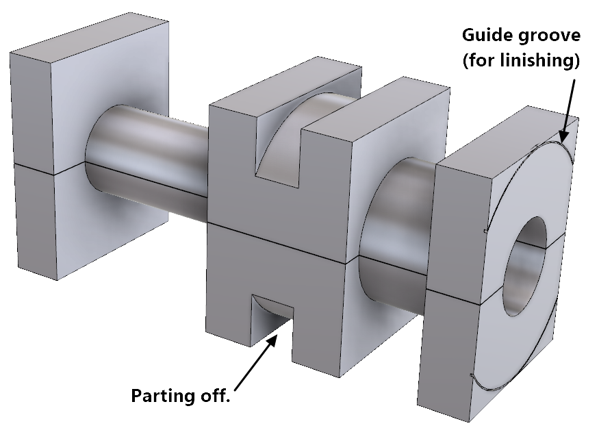
STEP 4 - Part-off the Hinge blocks. Machine a small groove at 40mm diameter in the end face of the block.This will act as a guide for a later linishing operation to remove some of the corners of the block. Lastly part off the Hinge Body piece to 32mm (max) long. Face-off the end of the Rotating Member (which is still in the chuck) such as to make its overall length 50mm (max). |
 |
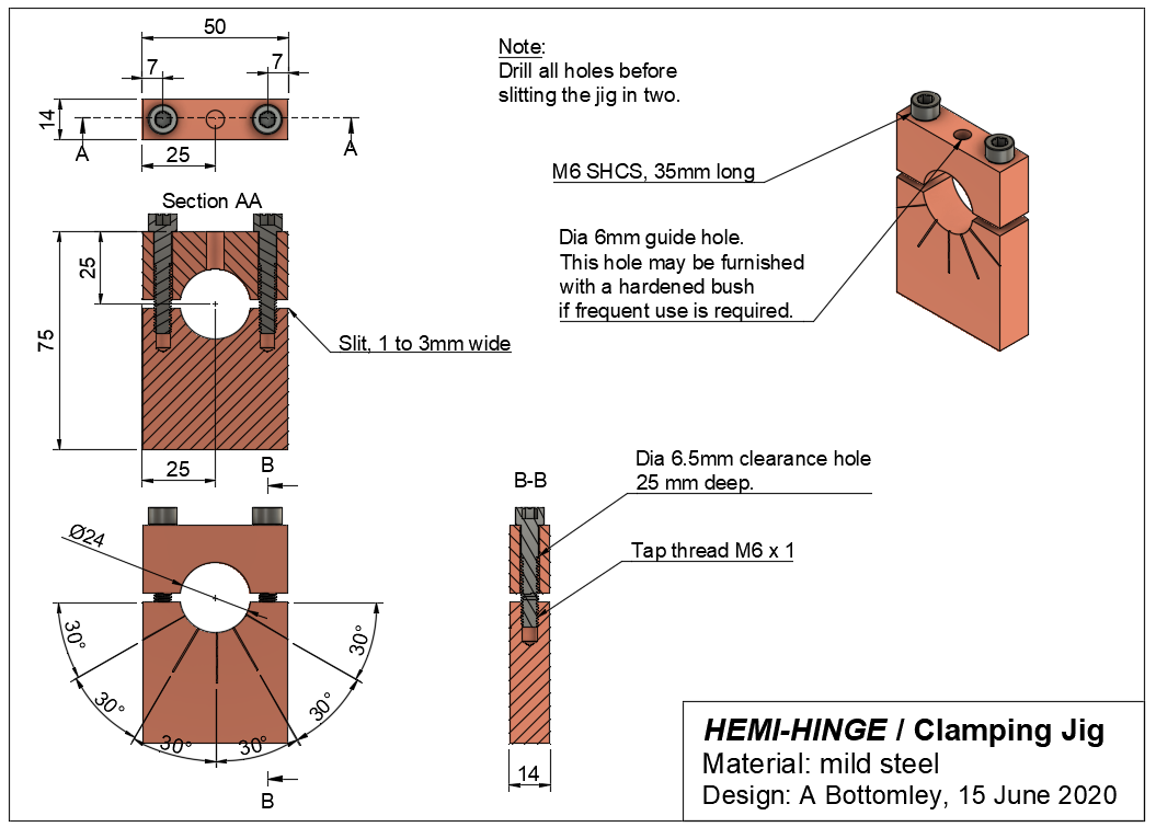
STEP 5 - Make a Clamping Jig. To implement the radial slot without any fancy machines will require the construction of a simple clamping jig. (Drawings for the jig are provided below). If the jig is to be used for making multiple hinges then the guide hole at the top should be provided with a hardened bush. The reference marks on the jig can just be scribed; they do not need to be super accurate. All holes should be drilled before the Clamping Jig is cut in two. |
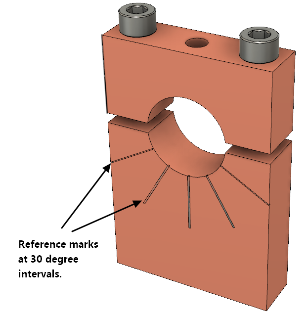 |
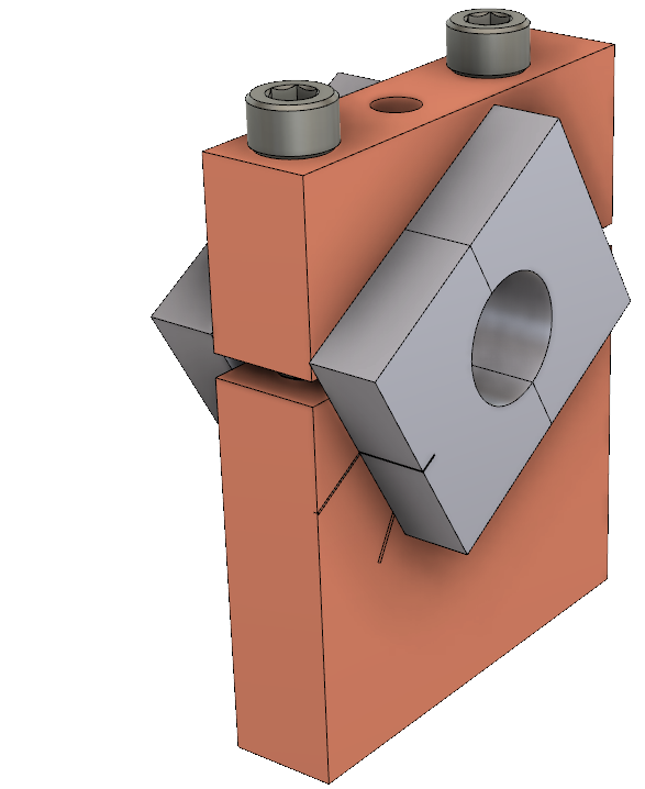
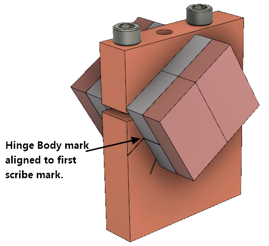
STEP 6 - Drill holes to form the radial slot. Clamp the Hinge Body in the jig as shown with the body reference mark aligned to the first scribe mark. Drill a 6mm hole right thru both halves of the hinge body. Loosen the clamp screws and rotate the hinge body to align with the next scribe mark and drill thru again. Repeat until all 5 holes are drilled. Note however that to prevent the drill bit from skewing off into an adjacent hole it is best to drill only every second hole initially and then drill the 2 remaining holes. Remove the Hinge Body from the jig. The operations above do not remove all the material for the radial slot but rather create a series of overlapping holes. Some filing will be required to complete the slot. |
 |
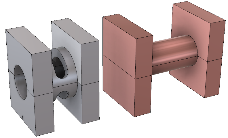
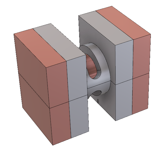
STEP 7 - Assemble the Hinge blocks Next we need to drill and tap the hole for the tension screw into the pivoting member. Fortunately we can do this using the same jig that was used for making the radial slot. Firstly take the hinge blocks and assemble them together as shown below on the right: |
|
  |
|
STEP 8 - Drill and tap the hole for the Tension Screw Now place the hinge assembly into the clamping jig and align the blocks as shown. Make sure the mark on the Hinge Body is aligned to the first scribe mark on the jig and that the Pivoting Member blocks are aligned to the Hinge Body as shown. After tightening the clamp screws spot drill thru the guide hole with a 6mm drill, then change to a 5.2mm drill bit and drill right thru both Pivoting members. Now tap an M6 thread thru the Pivoting Members. It is best to do this while the parts are still clamped together. |
 |
STEP 9 - Drill and tap mounting holes and linish corners. Drill and tap the holes for the M6 mounting bolts - 8 holes altogether. (Refer to drawings for dimensions). In the case of the Pivoting Member make sure the mounting holes are positioned on the side opposite the side with the tension screw hole. Linish the corners of each hinge block as shown. The linished surface is not a bearing surface; it just has to provide clearance for the hinge to operate. Do not remove any material from the flat surface around the mounting bolt holes. (A disc style linisher is effective for this operation). |
|
  |
|
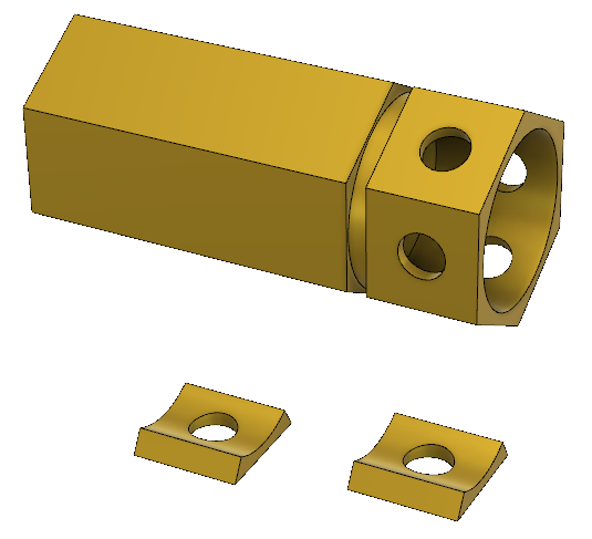
STEP 10 - Make the Bearing Shoes. An easy way to make the Bearing Shoes is to start with a 25mm (or 1") hex bar. The material is not critical but brass would be a good choice. With the bar in a lathe, drill a dia 22mm axial hole 16mm deep. Then drill 6mm cross holes in the centre of each flat face as shown. It is probably best to divide the pieces (eg by slitting with a fine-tooth hacksaw) before parting off at 14mm from the end. This will make 6 Bearing Shoes which is enough for three pairs of hinges. Note: With the sizes mentioned here the inner curvature of the shoe is not an exact match for the curvature on the hinge body, but over the short arc involved it is plenty close enough. |
 |
STEP 11 - Assemble the hinge. Smear the bearing surfaces of the hinge with molybdenum disulphide grease. Avoid getting grease on the threads of the tension screw. Assemble the Belleville disc to the tension screw making sure that the convex side of the disc washer is towards the head of the screw. Assemble the Bearing Shoe to the tension screw and insert the tension screw into the Pivoting Member. Tighten the tension screw until the Belleville disc is compressed flat and then back off the screw by about one fifth of a turn (70 degrees). This will give the hinge bearing the right amount of pre-load, about 30kg. Apply Loctite Wick-In (No.290) to lock the tension screw into the Pivoting Member. After the Loctite has set linish off the projecting part of the screw. Do not overheat the joint during linishing as that may weaken the Loctite. The hinge is now ready for mounting into your machine. |
|
 |
 |
Belleville washer specifications: 12.5 x 6.2 x 0.5mm (OD x ID x Thickness).
Preferably obtain alloy steel eg 60Si2Mn. Alloy steel has a better spring range than stainless steel.
A possible supplier for the Belleville washer: hkes-fastener.
_____________________________________________________________________________________
HEMI-HINGE
DRAWINGS
HINGE BODY:
Click here for a larger view or click here for HINGE BODY.PDF

HINGE PIVOT MEMBER:
Click here for a larger view or click here for HINGE PIVOT.PDF

HINGE CLAMPING JIG:
Click here for a larger view or click here for HINGE CLAMPING JIG.PDF

"Handyman" Index page.
Contact Alan Magnabend Homepage Alan's Homepage
This
page last updated: 8 August 2021